A buzzing sound or a door that refuses to lock often signals a need for immediate magnetic door lock repair in your facility. Unlike mechanical locks, these systems rely on electricity and precise alignment rather than moving parts to secure entryways.
This guide walks you through diagnosing power failures, correcting alignment errors, and silencing noisy units using basic tools. You will learn specific steps to restore security and ensure your access control system meets safety codes quickly.
Diagnose Power Supply Failure First

Over 60% of magnetic lock failures stem from power issues rather than defects in the lock itself. You must verify the energy source before disassembling any hardware components.
Test Voltage at Lock Terminals
Use a digital multimeter to check for 12V or 24V DC directly at the electromagnet terminals. Set your tool to DC voltage and touch the red probe to the positive wire and the black probe to the negative wire.
Readings below 10V for 12V systems or 20V for 24V systems indicate dangerous under-voltage conditions. Low voltage prevents full magnetic engagement and causes weak holding force. Common causes include:
* Failing power supply units
* Overloaded transformers
* Undersized wiring gauges
Replace the power supply immediately if output remains unstable or below specification. Always match voltage and amperage ratings to your specific lock requirements.
Verify Power Source and Fuses
Check that the outlet or circuit powering the supply is live and active. Some systems draw energy from building-wide access control panels, so verify those units are online.
Inspect internal fuses on the power supply board carefully. A blown fuse often indicates a short circuit in the wiring or the lock coil. Replace fuses only after isolating the short with a continuity test.
Pro Tip: Install a fused disconnect near the power supply for faster troubleshooting and safer maintenance in the future.
Fix Lock Engagement Failures

When the door fails to lock, the armature plate does not attract to the electromagnet properly. This compromises security and typically points to power loss, misalignment, or surface contamination.
Check Door Closure and Gap
Ensure the door closes fully without obstruction. A gap larger than 2 mm between the electromagnet and armature plate drastically reduces holding force. Use a feeler gauge to measure the distance accurately.
If the gap is too wide, follow these steps:
* Loosen mounting screws on the armature plate
* Slide the plate closer to the magnet without touching it
* Re-tighten screws and test the hold
Avoid zero clearance because direct contact can cause binding, especially if the door sags over time.
Clean Contact Surfaces
Dust, grease, or rust on the magnet face creates an air gap that weakens magnetic pull. These contaminants prevent the strong connection needed for security.
Wipe both surfaces with a dry microfiber cloth gently. For stubborn grime, use isopropyl alcohol on a cloth but never spray liquid directly onto the unit. Let the surfaces dry completely before testing engagement.
Warning: Corroded armature plates reduce effectiveness significantly. Replace the plate if pitting or flaking is visible on the surface.
Realign Magnet and Plate
Misalignment is a leading cause of engagement failure in commercial settings. Even slight angular deviation prevents full contact between components.
Use a spirit level to ensure the following:
* Electromagnet is perfectly horizontal and vertical
* Armature plate matches alignment exactly
Mark screw holes with tape before loosening them. Adjust one plane at a time, starting with horizontal then vertical. Retighten gradually to avoid shifting the components again.
Visual Cue: When aligned correctly, light should not pass between the two surfaces when the door is closed.
Resolve Lock Release Issues
A maglock that will not unlock is a serious safety hazard, especially on egress doors. Immediate action is required to free the door and restore fail-safe function.
Test Access Control Signal
Most locks disengage when the access panel sends a signal to cut power. Use the multimeter in continuity mode to test the signal wire effectively.
Have an assistant press the release button while you monitor the reading:
* If voltage drops to 0V, the signal is reaching the lock
* If voltage stays high, the control system is not sending the command
Check connections at the access panel and controller immediately. Reset the controller if it appears unresponsive to input.
Inspect Relay Operation
Relays switch power to the lock based on control signals from your access system. A stuck relay keeps the lock energized even when it should release.
Listen for a distinct click when the release button is pressed. No click suggests the relay may have failed internally.
Test the relay using this procedure:
1. Disconnect power to the system completely
2. Use multimeter in continuity mode across contacts
3. Activate the relay coil via test button or signal
4. Check if contacts open and close properly
Replace faulty relays with same-spec models immediately. Ensure coil voltage matches your system requirements of 12V or 24V DC.
Bypass for Emergency Release
In urgent cases, temporarily disconnect power at the supply unit. This forces release on fail-safe systems instantly.
For future prevention, install a manual override switch that cuts power locally. This is required by code on many egress paths to ensure safe evacuation.
Eliminate Intermittent Locking Problems

Random engagement or release points to unstable electrical connections within the system. These intermittent faults are frustrating but often easy to resolve with careful inspection.
Tighten Terminal Connections
Loose wires at the power supply, controller, or lock terminals cause flickering operation. Vibration from door slamming can loosen connections over time.
Turn off power before opening terminal blocks. Re-seat all wires and tighten set screws firmly. Ensure no stray copper strands are exposed to prevent short circuits.
Replace Damaged Cables
Inspect the full cable run for physical damage that could cause signal loss. Look for these specific issues:
* Crushed insulation in door frames
* Pinched wires near hinges
* Rodent damage in ceiling spaces
Use 18–22 AWG stranded copper wire for flexibility during installation. In high-noise areas near motors or elevators, upgrade to shielded cable to prevent interference.
Route cables away from AC power lines to reduce electromagnetic interference effectively.
Stabilize Voltage with Regulated Supply
Voltage ripple causes erratic behavior in sensitive electronic locks. Install a regulated power supply with built-in filtering to solve this.
These units maintain steady output even with input fluctuations from the building grid. They also protect against surges and brownouts that damage components.
Bonus: Regulated supplies often include LED indicators for power and lock status. Use these lights for quick diagnostics during future checks.
Silence Excessive Buzzing Noises
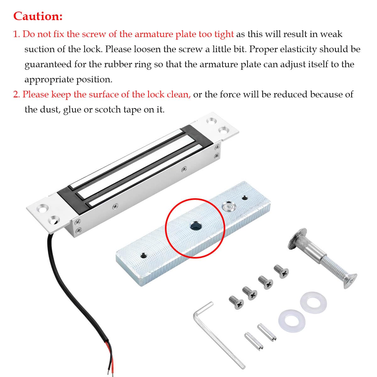
A loud hum or buzz from the maglock is not just annoying. It signals a problem that can lead to premature failure of the entire unit.
Correct Misalignment
Even minor misalignment causes the armature plate to vibrate against the magnet. This vibration creates the audible noise you hear.
Recheck parallelism using a spirit level again. Adjust until both components are flush when the door is closed tightly.
Pro Tip: Apply a thin layer of non-conductive damping tape on the armature plate to reduce resonance. Do not block magnetic contact with the tape.
Secure Loose Mounting
Vibrations from an unsecured electromagnet amplify noise levels significantly. Check all mounting screws on the frame and door.
Tighten firmly without over-torquing the hardware. Replace stripped screws with longer or thread-locking variants for a secure hold. Ensure the door frame is solid because hollow metal frames may need reinforcement.
Filter Dirty Power
“Dirty” power with voltage spikes causes rapid magnetic field fluctuations. This results in a loud buzzing sound from the coil.
Install a power line filter or noise suppressor at the supply output. These devices smooth DC output and block electromagnetic interference effectively.
Alternatively, replace an aging power supply with a high-quality, filtered model to eliminate the root cause.
Understand Fail-Safe vs Fail-Secure Modes
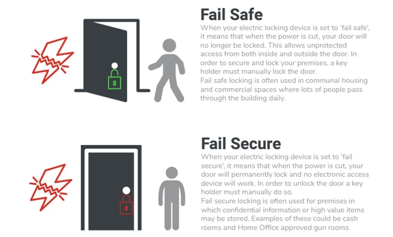
Understanding your lock’s operational mode is critical for safety and code compliance during repair. Installing the wrong mode can violate fire codes.
Identify Your Lock’s Mode
- Fail-Safe: Lock unlocks when power is lost. This is standard for emergency exits.
- Fail-Secure: Lock stays locked without power. This is used in high-security internal zones.
Check labeling on the electromagnet or controller to confirm your setup. Most commercial maglocks operate in fail-safe mode for safety.
Warning: Never install a fail-secure lock on a fire-rated egress door. This violates fire codes and endangers occupants.
Test During Power Loss
Simulate a power outage by unplugging the supply unit safely. Observe the door behavior closely.
If the door unlocks immediately, it is fail-safe. If it stays locked, it is fail-secure. Ensure fire alarm integration forces unlock on fail-safe systems during emergencies.
Backup Battery Use
Backup batteries keep fail-safe locks powered during outages. This maintains security without compromising safety during short power cuts.
Install UL-listed battery backup units with low-voltage monitoring features. Replace batteries every 2–3 years to ensure reliability.
Prevent Future Failures with Proper Installation
Many repair calls stem from poor initial installation practices. Correct setup ensures long-term reliability and reduces maintenance needs.
Mounting Best Practices
Use stainless steel screws to prevent corrosion over time. Anchor into solid framing and avoid hollow doors or weak frames.
Torque screws to manufacturer specs, typically 15–20 in-lbs. Over-tightening can warp the magnet housing and cause misalignment issues later.
Wiring Standards
Follow this wiring sequence for optimal performance:
1. Run shielded cable from power supply to controller
2. Connect controller to lock terminals securely
3. Ground shield at one end only to prevent ground loops
Label all wires at both ends for future troubleshooting ease.
Final Alignment Check
After mounting, close the door and slide a 1 mm feeler gauge between magnet and plate. Adjust until the gauge fits snugly.
Verify no light leaks around edges when the door is closed. This ensures optimal holding force without mechanical interference.
Maintain Your System Regularly
Routine checks catch small issues before they become major failures. A 5-minute monthly inspection saves hours of emergency repair work.
Monthly Inspection Checklist
Perform these checks every month:
* Tighten all mounting screws
* Clean magnet and armature surfaces
* Test release via card, keypad, and manual button
* Listen for buzzing or delayed response
* Inspect wires for fraying or damage
Document each check for compliance audits and facility records.
Annual Professional Service
Hire a licensed technician annually for a deep dive. They should test holding force with a pull gauge and verify fire alarm integration.
Ensure they inspect controller firmware and settings. Ask them to replace aging components proactively to prevent downtime.
Know When to Call a Professional
Some repairs require certified expertise, especially when dealing with complex systems. Do not attempt these fixes without proper training.
Call a pro for:
* Fire alarm integration issues
* Building-wide access control systems
* Code compliance verification
* Controller board replacement
Reputable service providers offer 24/7 emergency response and use UL-listed parts. Look for technicians who are licensed, bonded, and trained in major access control brands.
Frequently Asked Questions About Magnetic Door Lock Repair
Why is my magnetic door lock buzzing loudly?
Buzzing usually indicates misalignment, loose mounting, or dirty power. Check that the armature plate is parallel to the magnet and tighten all screws. If noise persists, install a power line filter or replace the power supply.
How often should I clean my magnetic lock contacts?
Clean the contact surfaces monthly or whenever you notice reduced holding force. Use a dry microfiber cloth to remove dust and grease. For stubborn grime, use isopropyl alcohol on the cloth, not directly on the unit.
What voltage do most magnetic door locks use?
Most commercial magnetic locks operate on 12V or 24V DC. Always check your specific model specifications before testing or replacing power supplies to avoid damage.
Can I install a magnetic lock on a fire exit door?
Yes, but it must be configured in fail-safe mode. This ensures the lock unlocks automatically if power is lost or the fire alarm activates, complying with life safety codes.
Why won’t my magnetic lock release when I press the button?
This often indicates a stuck relay, broken wire, or control signal failure. Test the relay for a clicking sound and verify voltage drops to zero when the button is pressed.
How do I know if my magnetic lock is fail-safe or fail-secure?
Simulate a power loss by unplugging the unit. If the door unlocks, it is fail-safe. If it remains locked, it is fail-secure. Most egress doors require fail-safe configuration.
Key Takeaways for Successful Magnetic Door Lock Repair
Effective magnetic door lock repair starts with checking the power supply, as most failures stem from voltage issues rather than mechanical defects. Proper alignment of the magnet and armature plate is equally critical for maintaining holding force and preventing noise.
Regular maintenance, including cleaning contacts and tightening screws, prevents most common problems before they compromise security. If you encounter complex wiring issues or fire code concerns, contact a licensed professional to ensure safety and compliance.